
Poor HVAC Airflow – Part 2
In part 1 of this blog series, we covered how the design of Heating, ventilation, and air conditioning (HVAC) systems can affect poor airflow.
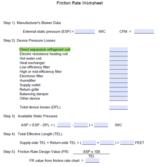
This discussion will focus on the devices located in the air stream of a residential HVAC duct system. These devices include coils, filters, registers, and grills. The primary focus will be on the first device that is typically listed in the Manual D Friction Rate Worksheet, the Direct Expansion Refrigerant Coil. It would be naive to suggest every new construction or retrofit residential installation include a complete design in accordance with ACCA Manuals J, D, and S. However, Dr. Energy does suggest every installation absolutely should include at a minimum, an analysis of the device pressure losses. Failure to ensure there is available static pressure for a duct system will result in a system that will never operate as intended.
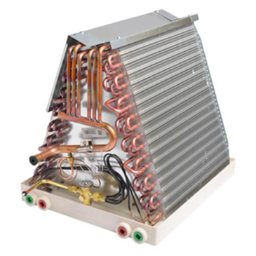
Referring to the Manual D Friction Rate Worksheet, Step 2, we find the Direct Expansion Refrigerant Coil listed first, highlighted in this example, as it is the most common device found now in almost every new home built in Utah. This coil, connected to the outdoor air conditioning condenser, removes excess summertime heat from the interior of the home, discharging that heat outside. Referring to the photo above, airflow from the furnace enters the bottom of the ‘A’ coil, splitting with the air passing through the aluminum fins on each of the two coil slabs attached to the coil tubing. Based on refrigeration principles we know that the coil is cold, and absorbs heat from the warm air stream, cooling that air which is discharged back into the home. Our concern in this discussion is the friction or pressure drop created as air moves through the tiny passages between the coil fins. We measure that pressure drop in inches of water column (IWC). It is also referred to as the inches water gauge (WG).
Assuming we are basing our design on a blower at 0.70 IWC, selecting a coil with a 0.30 or higher loss will result in a system that will never produce full capacity. Following the coil, we must account for the filter, registers, grills, and any other devices, hoping we have something left for the duct system. Too often, the wrong coil is selected, followed by a restrictive 1” filter, and finally with a poor duct system. Fan horsepower cannot fix that and as a result, the system will have poor airflow.
Let’s consider the wet pressure drop across several coils from a major manufacturer, where our target airflow is 1,200 CFM.
-
-
- 14” wide 3-ton coil @ 1,200 CFM: 0.335 IWC
- 17” wide 3-ton coil @ 1,200 CFM: 0.231 IWC
- 21” wide 3-ton coil @ 1,200 CFM: 0.160 IWC
- 17” wide 3.5-ton coil @ 1,200 CFM: 0.204 IWC
- 21” wide 3.5-ton coil @ 1,200 CFM: 0.165 IWC
- 17” wide 4.0-ton coil @ 1,200 CFM: 0.185 IWC
- 21’ wide 4-ton coil @ 1,200 CFM: 0.150 IWC
-
Obviously, selecting an oversized coil with the correct TXV refrigerant metering devices lowers the pressure drop across the device, improves airflow, increases efficiency, and improves customer comfort.
Please be cautious in selecting third-party manufacturers’ coils, especially when you notice the coil is shorter/smaller than the original equipment manufacturer (OEM) coils. You must verify the coil pressure drop. Dr. Energy’s recommendation is you only select split system components which you can certify system performance through the manufacturer’s expanded data or through the Air-Conditioning, Heating, and Refrigeration Institute (AHRI).
Lastly, many of you know Dr. Energy’s stance on the installation of a 5-ton residential split system, if you don’t, here it is: Do not install 5-ton systems, at our altitude, in our dry climate, with very little latent load, you simply cannot get enough air through the devices, filters, and duct systems to attain full capacity. Look up your furnace and air handler blower data, then compare it to this coil data:
-
-
- 21” wide 5-ton coil @ 2,000 CFM: 0.488 IWC
- 24” wide 5-ton coil @ 2,000CFM: 0.342 IWC
-
The pressure drop across these coils is simply too high, especially with the less-than-optimal furnace/air handler airflow. A key issue here is the manufacturer’s design equipment based on most of the country where there is humidity and high latent loads. Lower airflows provide increased latent capacity. Not our problem here where we are high and dry. We need the high air low to attain full rated sensible capacity and maximum energy efficiency. If calculations show there is a 60,000 BTU/hr. cooling load (5-ton), use two systems.
In summary, excessive pressure loss across devices leaves little if any available static pressure for the duct system. Perhaps it’s time to start testing the airflow through all residential systems, showing most of the systems installed in the past and today lack proper airflow.
Please continue your comments and questions. These discussions are based on comments received from you.
This discussion assumes the reader has some knowledge of residential HVAC systems, including ACCA Manual D – Residential Duct Systems, the procedure recognized by the American National Standards Institute (ANSI) and specifically required by residential building codes. This is written specifically for HVAC designers, HVAC contractors, plans examiners, inspectors, HERS raters, energy experts/testing personnel, and other interested parties.
– Dr. Energy
0 Comments