POOR HVAC AIRFLOW – PART 1
“I have a room in my house which is cold in the winter and hot in the summer, I need a bigger system!”
“My house isn’t cooling well so I hired a guy to put in a 5-ton air conditioner.”
No, you don’t need a bigger system. You have an airflow problem.
Low or incorrect airflow to individual rooms may cause reduced comfort, disturbing drafts, excessive noise, poor circulation/uneven temperatures, frozen coils, excessive energy consumption, and shortened equipment life. A larger system with an already deficient duct system will only exacerbate problems.
During the past year, heating, ventilation, and air conditioning (HVAC) contractors, code officials, home builders, and even the Utah Legislature have discussed residential home comfort complaints and concerns; ultimately focusing on the most significant problem found in residential HVAC systems – insufficient airflow, directly related to the duct design, duct installation, and other airflow related issues. Dr. Energy’s favorite analogy to use to help people understand airflow issues is this: You can have great water pressure at the hose bibb, but if the hose is kinked (multiple times), the flow out the end will be low. Increasing water pressure increases turbulence, further reducing flow at the nozzle. This concept also applies to HVAC systems an air conditioner will only deliver at its full capacity when the duct system is designed to allow free airflow.
Dr. Energy often receives phone calls and emails with questions from system designers, builders, HVAC contractors, and building departments regarding Manual J, D, and S designs submitted for building permits. A common concern centers on the installation not matching the design, especially where the design requires efficient duct fittings direction of airflow through elbows, offsets, and transitions. Too often turning and twisting the duct elbow design mandates turning vanes or radiused throats, but the installation includes only square inside throats without turning vanes. This is a serious concern and the source of many cooling problems, the most significant are reduced cooling capacity, lack of comfort, and excessive energy consumption.
Considering that garden hose again, the longer the hose, the greater the friction, and the lower the flow. Say one has a hose reel on the side of their home with a 100’ hose neatly rolled up. If you turn on the water with virtually all the hose rolled on the reel, the flow is much lower than if it were rolled it out straight, with smooth gradual bends. For duct systems, in Manual D, we find principles and tables identifying the pressure loss through the length of the duct, including an equivalent duct length for numerous duct fittings.
Let’s consider three plenum elbows, the first turn off the top of the furnace or air handler, and the most critical fitting in a system. These fittings may be designed with a square inside throats, with turning vanes, or with the radiused inside the throat. Courtesy Manual D, we have these graphics from Group 1 Supply Air Fittings, the first fitting immediately off the air handler
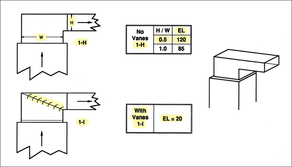
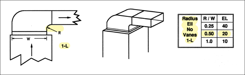
FIGURE 1
- Please note each fitting style is identified with a Group number and a letter, such as 1-H, 1-I, or 1-L.
- 1-H, square inside throat, H/W ratio of 0.5 is equivalent to the friction produced in 120’ of straight duct.
- 1-I, square inside throat with turning vanes, EL (equivalent length) is 20’.
- 1-L, radiused inside throat, R/W ratio of 0.5, EL is 20’.
- 1-L, radiused inside throat, R/W ratio of 1.0, EL is 10’.
That 1-H square throat used in many new residential systems installed today is at least 6 times as restrictive as turning vanes or radiused throats. The pressure loss through that 1-H plenum elbow is equivalent to the pressure loss realized through 100 feet of straight duct! Hopefully, those businesses focusing on retrofits, the replacement of HVAC furnaces and air conditioners, consider improving the airflow by modifying the plenum elbows and tees as these are often the only duct fittings accessible. With these changes, the system’s performance will undoubtedly improve.
Manual D includes guidance on virtually every fitting in a residential HVAC duct system, identified in Groups 1 to 13; however, we will let’s consider just one more, Group 8 Elbows and Offsets, in the main duct trunks.
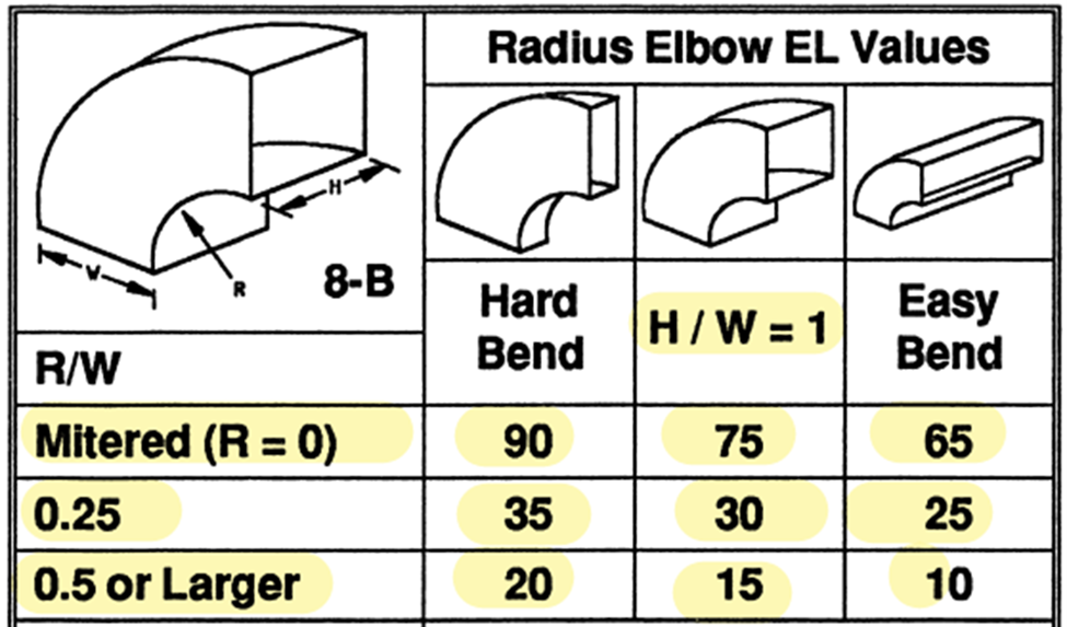
FIGURE 2
- 8-B, mitered (R = 0) represents a square throat. EL = 90’ for a hard bend/horizontal elbow, 65’ for an easy bend/vertical elbow.
- 6” radiused throat on an 8X12 duct, R/W 0.50. EL = 20 for a hard/horizontal bend, 10’ for an easy/vertical elbow.
- 6” radiused throat on an 8X24 duct, R/W 0.25. EL = 35 for a hard/horizontal bend, 25’ for an easy/vertical elbow.
Returning to the earlier comments on the installation not matching the design, Wrightsoft and other HVAC Load Calculation Software now include a list of the fittings used in the design. The image below is an example from a Wrightsoft Duct Design. Please note each fitting Group number is called out with its equivalent length (EL) as detailed in ACCA Manual D.

FIGURE 3
Looking up the highlighted 8E in Manual D, we find the elbow requires turning vanes to attain a 10’ equivalent length. Unfortunately, the installation rarely includes the turning vanes. Realizing how cumbersome it is to identify the fitting group number, Wrightsoft is being contacted to see if a fitting image report can be generated, providing direction to the fabricator, installer, and inspector. Also, notice there is a Total EL for the supply and the return system. Combined, we have in the example a total EL of 560’. Sadly, when this system is installed with the incorrect fittings, the Total EL may approach and exceed 1,000’. Adjusting the charge, increasing fan hp, adding frost stats to stop the coil freezing, or blaming it on the inspector or the equipment won’t fix it. It’s too often an airflow problem.
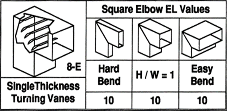
FIGURE 4
Please watch for additional discussion on this subject, including education and possibly some system testing studies. If you don’t have a copy of Manual D, consider getting one.
In Part 2 of the airflow discussion, the subject will be focused on the importance of properly accounting for the pressure drop across devices, such as evaporator coils mounted at the furnaces, filters, registers, and grills. In that discussion, we’ll identify how minimizing the pressure drop across these devices, located in the air stream, ensures sufficient external static is available for the duct system. Ultimately, properly applying all the design and installation procedures in Manual D will ensure the correct airflow throughout a home, at the CFM (volume) calculated based on ACCA Manual J.
Please feel welcome to ask questions, share your thoughts or express your concerns.
– Dr. Energy
0 Comments