Author: Brent Ursenbach
This code discussion is based on the 2015 International Residential Code (IRC) as currently adopted,
including Utah Amendments where applicable. State Amendments to sections from IRC code quoted are identified with red text. Italics indicate quoted code sections. Please note this discussion briefly addresses only specific issues identified in the limited number of photos provided and conversations with the homeowner. This must not be considered a complete code compliance inspection or analysis of the entire home discussed here.
The owner of a new home, located in Climate Zone 6 Box Elder County, is experiencing discomfort in the home and high utility bills posed questions and comments regarding poor comfort and high utility expense in the home. He explains, in the winter season, with the furnace located in the garage at one end of the home, the furthest other end of the home is always the coldest. He provided the attached photos, which quickly identified several IRC code compliance issues with the crawl space ventilation, insulation and duct systems located within the crawlspace. Further, with the furnace and uninsulated duct located outside the building thermal envelope, the entire system also lacks any observable form of required duct sealing or any indication required duct pressure testing was performed, ensuring the ducts have been sealed to minimize duct leakage.
First, a review of several chapters and sections in the IRC will identify specific code requirements.
IRC Chapter 4 Foundations
Section R408 Under-Floor Space requires ventilation of these spaces, to minimize the formation of moisture condensation on the floor and wall components. The major source of moisture is the ground below, where even in desert climates, moisture from deep below grade is always migrating to the surface. This section also provides an option for an unvented crawlspace.
IRC R408.1: Ventilation. The under-floor space between the bottom of the floor joists and the earth under any building (except space occupied by a basement) shall have ventilation openings through foundation walls or exterior walls. The minimum net area of ventilation openings shall be not less than 1 square foot (0.0929 m2) for each 150 square feet (14 m2) of under-floor space area unless the ground surface is covered by a Class 1 vapor retarder material. Where a Class 1vapor retarder material is used, the minimum net area of ventilation openings shall be not less than 1 square foot (0.0929 m2) for each 1,500 square feet (140 m2) of under-floor space area. One such ventilating opening shall be within 3 feet (914 mm) of each corner of the building.
R408.2 Openings for under-floor ventilation. The minimum net area of ventilation openings shall be not less than 1 square foot (0.0929 m2) for each 150 square feet (14 m2) of under-floor area. One ventilation opening shall be within 3 feet (915 mm) of each corner of the building. Ventilation openings shall be covered for their height and width with any of the following materials provided that the least dimension of the covering shall not exceed 1/4 inch (6.4 mm):
1. Perforated sheet metal plates not less than 0.070 inch (1.8 mm) thick.
2. Expanded sheet metal plates not less than 0.047 inch (1.2 mm) thick.
3. Cast-iron grill or grating.
4. Extruded load-bearing brick vents.
5. Hardware cloth of 0.035-inch (0.89 mm) wire or heavier.
6. Corrosion-resistant wire mesh, with the least dimension being 1/8 inch (3.2 mm) thick.
Exception: The total area of ventilation openings shall be permitted to be reduced to 1/1,500 of the under-floor area where the ground surface is covered with an approved Class I vapor retarder material and the required openings are placed to provide cross ventilation of the space. The installation of operable louvers shall not be prohibited.
R408.3 Unvented crawl space. Ventilation openings in under-floor spaces specified in Sections R408.1 and R408.2 shall not be required where the following items are provided:
1. Exposed earth is covered with a continuous Class I vapor retarder. Joints of the vapor retarder shall overlap by 6 inches (152 mm) and shall be sealed or taped. The edges of the vapor retarder shall extend not less than 6 inches (152 mm) up the stem wall and shall be attached and sealed to the stem wall or insulation.
2. One of the following is provided for the under-floor space:
2.1. Continuously operated mechanical exhaust ventilation at a rate equal to 1 cubic foot per
minute (0.47 L/s) for each 50 square feet (4.7 m2) of crawl space floor area, including an air
pathway to the common area (such as a duct or transfer grille), and perimeter walls insulated in accordance with Section N1102.2.11 of this code.
2.2. Conditioned air supply sized to deliver at a rate equal to 1 cubic foot per minute (0.47 L/s) for each 50 square feet (4.7 m2) of under-floor area, including a return air pathway to the common area (such as a duct or transfer grille), and perimeter walls insulated in accordance with Section N1102.2.11 of this code.
Summarizing the two options for controlling possible moisture condensation and the resulting mold growth in these under-floor spaces:
Option 1: Ventilate the space with a natural flow of outside air through foundation wall vents,
sized according to the code. The openings must be located to ensure the entire space will cross ventilate including corners. Using this option creates an unconditioned, outside temperature
environment under the floor of the living space, triggering floor and duct insulation requirements per IRC Chapter 11.
Option 2: Create a conditioned under-floor space, where the thermal envelope extends down
the foundation stem walls down to the top of footings, with crawl space wall insulation per
Chapter 11. For this option, it is critical that the vapor retarder is carefully sealed at all joints and
sealed to the foundation stems walls. Experience shows that closed cell foam must be sprayed,
at least 2” thick in all rim joist areas, to prevent the formation of condensation and mold on the
rim joist. Additionally, either a continuously running exhaust fan, or flow of air from the HVAC
system must be installed to provide a minimum volume of air circulation and ventilation
between living space and the crawlspace.
With each of these two options, there are unique specific energy code requirements, found in IRC
Chapter 11, which reduce energy consumption, increase HVAC appliance efficiency and life, and
dramatically improve occupant comfort.
Crawl Space Insulation, Ducts, and Water Lines
IRC Chapter 11- Energy
This chapter details the minimum required level of insulation for all components of the building thermal envelope. The building thermal envelope is defined as the walls, floors, roof/ceiling, and any other building elements such as windows, doors, skylights, that enclose conditioned spaces. The insulation which was added to the walls of the crawlspace provides no real value as the crawlspace is ventilated with outside air. Another concern, the water lines located within the crawlspace, exposed to cold possibly freezing temperatures.
If Option 1 above is selected, the floor is a component of the thermal envelope and must be insulated as further outlined in this chapter. Additionally, the entire sheet metal duct system is located outside the thermal envelope, requiring insulation complete with a vapor barrier, as also defined in this chapter. This insulation minimizes the heat loss from the duct to the cold crawl space, providing much warmer air to the registers in those rooms furthers from the furnace.
If Option 2 is selected, the crawl-space walls must be insulated per this chapter, including the rim joist areas and along with all the vapor barrier and mechanical ventilation requirements found in Chapter 4.
Reviewing the applicable Chapter 11 requirements:
N1102.1.2 Insulation and fenestration criteria. The building thermal envelope shall meet the requirements of Table N1102.1.2 based on the climate zone specified in Section N1101.7.

Please note the Climate Zones (CZs) in this Table are based on temperature extremes. Lower numbers are hot, cooling dominated climates while higher number are colder, heating dominated climates. Washington County (St. George) is CZ 3, the northern and higher elevation Counties including Box Elder, are CZ 6, with most of the state CZ 5. If Option 1 is selected, the floor should be insulated to a minimum R-30. If Option 2 is selected, the crawlspace walls must be insulated to a minimum R-15 if continuous foam or blanket insulation is used. If the walls are framed and insulation placed in stud cavities, the minimum value is R-19. This wall insulation must extend to at least 2’ below the finished grade on the exterior side of the wall. All vertical wall insulation must include an air barrier.
Next is duct insulation where the duct is outside the thermal envelope (Option 1). All ducts in the
furnace room and the crawlspace including round pipe, elbows, and boots require minimum R-6
insulation. Any portions of the duct located in the attic must be insulated to R-8.
N1103.3.1 Insulation (Prescriptive). Supply and return ducts in attics shall be insulated to a minimum of R-8 where 3 inches (76.2 mm) in diameter and greater and R-6 where less than 3 inches (76.2 mm) in diameter. Supply and return ducts in other portions of the building shall be insulated to a minimum of R-6 where 3 inches (76.2 mm) in diameter or greater and R-4.2 where less than 3 inches (76.2 mm) in diameter.
Exception: Ducts or portions thereof located completely inside the building thermal envelope.
The last insulation issue with a ventilated crawlspace is the waterlines. Chapter 11 requires hot water piping insulation to reduce the wasted heat off the piping while Chapter 26 details protection from freezing for all plumbing piping.
N1103.5.3 Hot water pipe insulation (Prescriptive). Insulation for hot water pipe with a minimum thermal resistance (R-value) of R-3 shall be applied to the following:
1. Piping 3/4 inch (19 mm) and larger in nominal diameter.
2. Piping serving more than one dwelling unit.
3. Piping located outside the conditioned space.
4. Piping from the water heater to a distribution manifold.
5. Piping located under a floor slab.
6. Buried piping.
7. Supply and return piping in recirculation systems other than demand recirculation systems.
P2603.5 Freezing. In localities having a winter design temperature of 32°F (0°C) or lower as shown in Table R301.2(1) of this code, a water, soil, or waste pipe shall not be installed outside of a building, in exterior walls, in attics or crawl spaces, or in any other place subjected to freezing temperature unless adequate provision is made to protect it from freezing by insulation or heat or both. Water service pipe shall be installed not less than 12 inches (305 mm) deep and not less than 6 inches (152 mm) below the frost line.
The last major concern is duct sealing and testing for leakage. Joints and seams in supply ducts that leak to outside the thermal envelope result in simply throwing away heated or cooled conditioned air. Where return ducts leak, outside air, or in the case of a system located in a garage, harmful fumes might be brought into the home. The code provided direction for sealing the ducts, following with testing
requirements.
N1103.3.2 Sealing (Mandatory). Ducts, air handlers and filter boxes shall be sealed. Joints and seams shall comply with either the International Mechanical Code or Section M1601.4.1 of this code, as applicable.
Exceptions:
1. Air-impermeable spray foam products shall be permitted to be applied without additional joint seals.
2. For ducts having a static pressure classification of less than 2 inches of water column (500 Pa),
additional closure systems shall not be required for continuously welded joints and seams, and locking-type joints and seams of other than the snap-lock and button-lock types.
M1601.4.1 Joints, seams, and connections. Longitudinal and transverse joints, seams and connections in metallic and nonmetallic ducts shall be constructed as specified in SMACNA HVAC Duct Construction Standards—Metal and Flexible and NAIMA Fibrous Glass Duct Construction Standards. Joints, longitudinal and transverse seams, and connections in ductwork shall be securely fastened and sealed with welds, gaskets, mastics (adhesives), masticplus-embedded fabric systems, liquid sealants, or tapes. Tapes and mastics used to seal fibrous glass ductwork shall be listed and labeled in accordance with UL 181A and shall be marked “181A-P” for pressure-sensitive tape, “181 A-M” for mastic or “181 AH” for heat-sensitive tape.
N1103.3.3 (R403.3.3) Duct testing (Mandatory). Ducts shall be pressure tested to determine air leakage by one of the following methods:
1. Rough-in test: Total leakage shall be measured with a pressure differential of 0.1 inch w.g. (25 Pa) across the system, including the manufacturer’s air handler enclosure if installed at the time of the test. All registers shall be taped or otherwise sealed during the test.
2. Postconstruction test: Total leakage shall be measured with a pressure differential of 0.1 inch w.g. (25 Pa) across the entire system, including the manufacturer’s air handler enclosure. Registers shall be taped or otherwise sealed during the test.
Exception: A duct air leakage test shall not be required where 80% of the ducts and air handlers are located entirely within the building thermal envelope. A written report of the results of the test shall be signed by the party conducting the test and provided to the code official. The following parties shall be approved to conduct testing: Parties certified by BPI or RESNET, or licensed contractors who have completed training provided by a duct testing equipment manufacturer or comparable training.
N1103.3.4 (R403.3.4) Duct leakage (Prescriptive). The total leakage of the ducts, where measured in accordance with Section R403.3.3, shall be as follows:
1. Rough-in test: The total leakage shall be less than or equal to 6 cubic feet per minute per 100 square feet (9.29 m2) of conditioned floor area where the air handler is installed at the time of the test. Where the air handler is not installed at the time of the test, the total leakage shall be less than or equal to 6 cubic feet per minute) per 100 square feet (9.29 m2) of conditioned floor area.
2. Postconstruction test: Total leakage shall be less than or equal to 6 cubic feet per minute per 100 square feet of conditioned floor area.
Conclusions: The homeowners concerns are legitimate, as there are several major energy code compliance issues which are creating the reported conditions. Additionally, this discussion illustrates the importance in considering all sections of the IRC in the design and construction of a home. The primary focus here is Chapter 11, Energy; however, the building, mechanical and plumbing provisions of the IRC are integral to the discussion. Please consider the following:
1. The home as constructed includes a ventilated crawlspace as defined in Option 1 above. Assuming the intent is to maintain a vented crawlspace, the following must occur to for code compliance:
a. A minimum R-30 insulation add to the entire floor system. Insulation must be full depth without voids at the rim joist.
b. The entire duct system including rectangular ducts sealed. Ensure sealing occurs at the connections to the furnace, coil cabinet, and filter cabinet which lacks a door/cover.
c. With the furnace located in the garage, outside the thermal envelope, as well as virtually all the duct systems, the duct systems must be pressure tested, ensuring duct sealing has reduced leakage to less than 6 CFM per 100 sq. ft. of conditioned floor area.
d. Insulate all duct systems outside the thermal envelope with a minimum of R-6 foil backed duct wrap. If any portions of the duct are in the attic, a minimum R-8 is required.
e. Insulate all water lines exposed to the cold conditions in the crawlspace.
2. If Option 2 is selected, creating an unvented, conditioned crawlspace, the following must occur for code compliance:
a. The openings for the foundation vented filled in and sealed.
b. The insulation R-value on the walls brought up to a minimum R-15 continuous, with an air barrier added over the face of the insulation.
c. Provide a fully taped and sealed vapor barrier across the exposed earth, sealed to the stem walls as defined in the code. Ensure sharp rocks which will penetrate the vapor barrier are removed or covered with clean/fine material.
d. As it is virtually impossible to add a sealed air barrier over the face of insulation in the small cavity sections of the rim joist, which must also have a minimum R-value of R-19 due to being in a cavity, provide R-19 closed cell spray foam in the rim joist areas.
e. Seal the duct system as detailed above.
f. Provide duct system pressure testing as the furnace is located outside the thermal envelope.
g. Provide either a continuously operating exhaust fan or ventilation/circulation through the HVAC system per code requirements.
A final comment on the unvented conditioned crawlspace option, which first appeared in this general form in the 2003 IRC. As there have been numerous issues with this option, this section of the code has been continuously improved, modified or clarified for each subsequent 3-year code cycle, including the most recent but not Utah adopted 2018 and 2021 editions of the IRC. If this option is selected for use in the design and construction of a building, contractors and code officials need to be vigilant in ensuring compliance with all code requirements. Especially critical is the vapor barrier over the earth, the use of spray foam on the rim joist cavities and providing continuous ventilation with an exhaust fan or the HVAC system. Failure to carefully and completely address each item noted in R408.3 Unvented Under-floor Spaces will result problems with mold in these rim joist areas. Please see the last photo examples of mold from another home, at the end of the attached photos.
The discussion has been written to provide energy code education and assistance to design professionals, contractors, sub-contractors, building inspectors, plans examiners, and the public at large. Please refer comments and questions to Brent Ursenbach at: [email protected] or [email protected]
Photo Provided by Homeowner
- One of several open foundation vents
- What value is the wall insulation with multiple openings to outside?
- Ineffective vapor barrier installation – open seams, no overlap, no sealing, incomplete at the edges

Photo Provided by Homeowner
- Limited number of pictures –
cannot determine if ventilation
openings are sufficient and
large enough - Closing the foundation vents
will create moisture issues if all
insulation, sealing, vapor and
air barrier requirements are not
precisely met

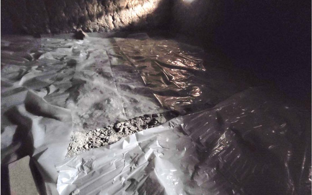
Photo Provided by Homeowner
- Enlarged section of previous
photo - Rock under plastic vapor
retarder appear to have
sharp edges which may
easily cut through the
plastic - Construction debris can also
damage the vapor retardert

Photo Provided by Homeowner
- Incomplete vapor retarder
- Construction debris left in
the crawlspace

Photo Provided by Homeowner
Photo From a Different Home
- Uninsulated duct in the vented crawlspace
- Also uninsulated water lines
- No apparent sign of duct sealing
- If the wall insulation was installed as an attempt to create an unvented conditioned crawlspace, the insulation requires an air barrier over the face of the insulation
- Photo on the right from another location, shows a proper vapor retarder on the ground and a rigid board air impermeable insulation


Photo Provided by Homeowner
- Another photo provided by the homeowner
- Incomplete vapor retarder
- No air barrier on the wall insulation or rim joist insulation
- Uninsulated water line

Photo Provided by Homeowner
Photo Provided by Homeowner
- Furnace located in room in garage, outside the thermal envelope
- If the furnace or air handler is located outside the thermal envelope, duct pressure testing is required
- There is no indication any sealing occurred at any duct connections
- Filter frame lacks cover resulting in a significant leak, possibly drawing hazardous fumes from garage into the home


Photo Provided by Homeowner
- Duct pressure testing historically shows significant leakage occurs at the evaporator coil connection to the
furnace - No apparent effort to seal this
connection

Photos From a Different Home
- Photos from a one‐year‐old home
- The contractor attempted to create an unvented crawlspace
- Vapor barrier on earth was not sealed
- HVAC ventilation was confined to a small area near the furnace – did not circulate through the entire crawlspace
- Rim joist insulation was only a
loose batt, with no air barrier
covering – insulation was
ineffective - Mold heaviest on the rim joist


Photos From a Different Home
- With the ineffective rim insulation, lack of proper exhaust or HVAC ventilation/circulation, and unsealed vapor barrier on the earth, mold was prevalent throughout crawlspace
- The fix required:
- Replace and seal vapor barrier
on earth, sealing to foundation
walls - Dry ice blasting the mold off
the wood - Application of a mold
treatment solution - Closed cell spry foam
application on all rim joist
areast
- Replace and seal vapor barrier

