Forced Air Heating & Cooling Systems – Energy Efficient Duct Installation Practices
Previous discussions have reviewed ACCA/ANSI Manual D – Residential Duct Systems, primarily focusing on pressure drops across devices, duct sizing, and fitting design. This discussion will concentrate on installation practices as identified in the SMACNA – HVAC Duct Construction Standard.
In a recent investigation into complaints of poor airflow in a residential installation, excessive duct leakage was identified as the primary reason airflow at return inlets and supply outlets tested at far below the design volume. With a design airflow of 1,000 CFM, duct testing showed actual return CFM measured at 365 CFM and actual supply CFM at 740 CFM. The duct leakage was so high that the duct blaster fan was only able to achieve a 10-pascal pressure within the duct. If the fan was able to raise the test pressure to the typical 25-pascals, leakage would be even higher. With massive leakage identified at the plenum/trunk connections, the areas around the furnace room are marginally comfortable, but the living space around the perimeter of the home does not heat or cool. Unfortunately, these leakages are causing the home to experience increased energy consumption and poor comfort.
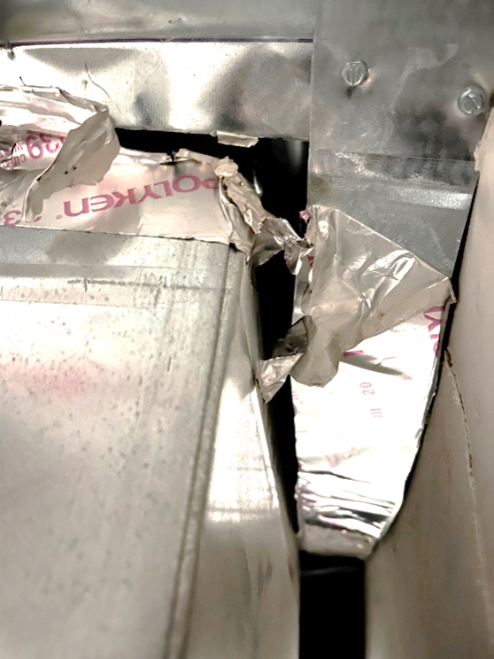
The attached photos identify obvious leaks where the plenum tapped into the bottom of the main trunk using sheet metal patches and tape. It is painfully obvious why the supply airflow at the registers is poor as gaps up to ¾” wide were observed in several locations. Please notice the dirt on top of the coil and in the duct. This is a 6-month-old house, with the furnace used for construction heat without a properly sized filter.
(Photos by Brent Ursenbach)
View looking down into the plenum from above:
View looking down into the plenum from above:

View from below, facing up, from outside the plenum:

Referring to the currently adopted Codes:
2015 International Residential Code (IRC), Chapter 11, N1103.3.2 (IECC R403.3.2) Sealing:
Ducts, air handlers, and filter boxes shall be sealed. Joints and seams shall comply with either the International Mechanical Code or Section M1601.4.1 of this code, as applicable.
2015 IRC, Chapter 16, M1601 Duct Construction Subsection M16001.1.1 (3):
Field-fabricated and shop-fabricated metal and flexible duct constructions shall conform to the SMACNA HVAC Duct Construction Standards—Metal and Flexible except as allowed by Table M1601.1.1. Galvanized steel shall conform to ASTM A 653.
As many do not own a copy of SMACNA, the following summarizes several important rectangular duct specifications:
-
- All transverse duct joints/connections shall be made with s-cleats or a combination of s and drive cleats.
- Where s-cleats are used on all four sides, screws are required within 2” of corners and 12” on centers.
- Larger ducts, typically commercial, may require standing cleats.
- Fittings and tap-ins may use clinch/hammerlock connections.
- Provide flanges for connections to coils, air handlers, and other equipment.
- Seal all connections per SMACNA and the IECC.
- Listed UL-181 tape is a duct sealer, not a substitute for sheet metal, cleats, and fasteners. It is for use after a secure, relatively tight
connection has been made. Notice in the second photo where foil tape was spanning large gaps, the tape has failed. - Flanged/butted connections (such as at plenum to equipment connections) should include gaskets and sealers as connections
are being made. - Refer to the manufacturer’s installation instructions for specific equipment requirements.
Watch for future discussion from SMACNA and other standards on correct duct construction practices, including duct reinforcement, turning vanes, round ducts, hangers, and supports. Of course, your questions, comments, and suggestions are always welcome.
– Dr. Energy

0 Comments